Note: Uses images from Computer Organization and Design By John L. Hennessy, David A. Patterson
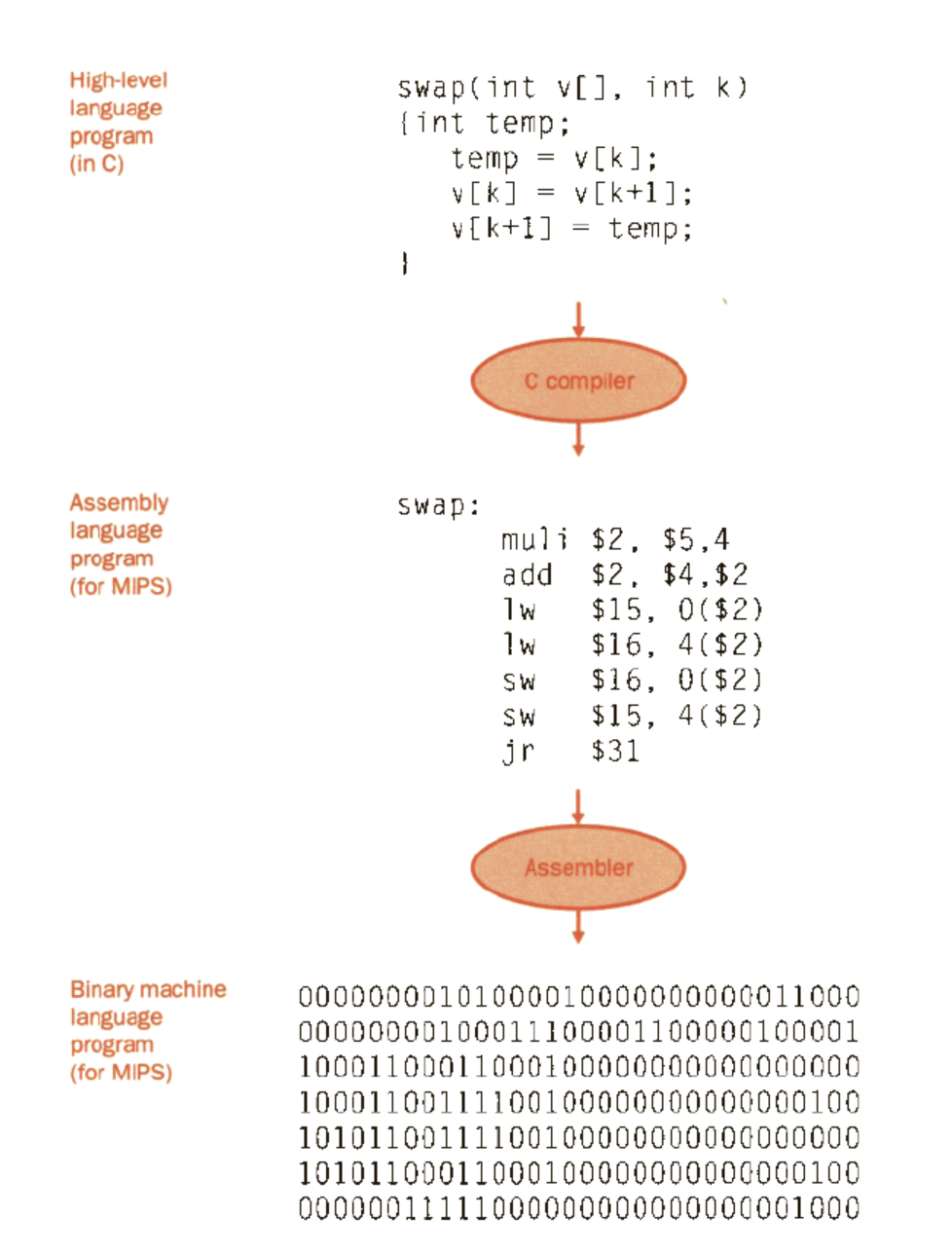
From high level to machine code
- High-level language program
- Assembly language program
- Binary machine language program
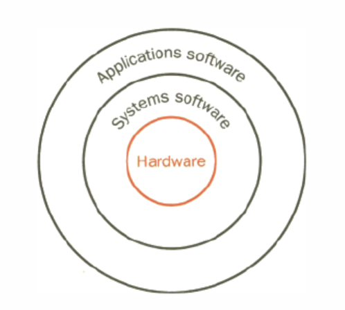
Simple view of layers of hardware and software
Key Metrics
- Clock period: duration of a clock cycle, basic unit of time for all computers
- ex 250ps = 0.25ns
- Clock frequency (rate): cycles per second
- ex: 4.0GHz
- Execution Time = (cycles per program / clock rate)
- Performance Metrics:
- Perf(A, P) = 1 / Time(A, P) where machine A is running a program P
- For two computer A and B, on the same program P:
- Perf(A, P) > Perf(B, P) → Time(A, P) < Time (B, P)
- A is n times faster than B if n > 1
- (Perf(A, P) / Perf(B, P)) = (Time(B,P)/Time(A,P)) = n
- Speedup = Time(old) / Time(new)
- Speedup Efficiency = speedup / n
- Does throughput = 1 / latency
- can do only one thing at a time: yes
- can do more than one thing at a time: no
- Little’s Law: parallelism
- parallelism = throughput x latency
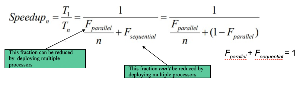
- Amdahl’s law: the max speedup considering sequential ops
- Instruction count and CPI
- clock cycles = instruction count x cycles per instruction
- CPU time = instruction count x CPI x clock cycle time = (instruction count x CPI) / clock rate
- Instruction count (IC) - determined by program, ISA and compiler
- Average cycles per instruction (CPI) - hw design
- Iron Law: CPU performance equation
- Two ways of putting it:
- execution time = (instruction/program) x (clock cycles/instruction) x (seconds / clock cycle)
- execution time = IC x CPI x clock cycle time
- must take all 3 factors into account
- high perf or low exec time depends on:
- algo, pl, compiler, ISA, hw design
- Two ways of putting it:
- Calculating cycles per instruction (CPI)
- CPI =
- CPI =
- Weighted average:
- CPI = sum( x ( / )
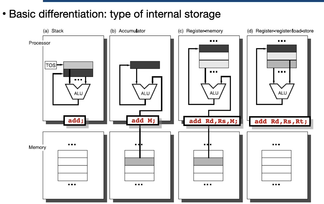
ISA
Definition
the hardware/software interface defines:
- the state of the system (registers, memory)
- functionality of each instruction: add, sub, load, etc
- encoding of each HW instruction does not define:
- how instructions are implemented by HW
- how fast/slow instructions are
- how much power instructions consume
Classes
| Class (category) | Typical instructions | Reason for grouping |
|---|---|---|
| ALU / Arithmetic & Logic | add, sub, and, or, slt… | All use only the ALU; usually 1 cycle. |
| Load | lw, ld | Need a memory read; often 2+ cycles. |
| Store | sw, sd | Need a memory write; often 2+ cycles. |
| Branch / Jump | beq, bne, j | May cause control hazard; extra cycles if mispredicted. |
| Floating point | fadd, fmul | Use floating-point unit; often more cycles. |
Fixed Length vs Variable Length ISAs
Think like tradeoffs in memory alloc in OS (internal fragmentation vs external fragmentation) Fixed Length ISAs
- address of next instruction is easy to compute
- poor code density Variable Length ISAs
- better code density
- fetch and decode are more complex
RISC vs CISC
CISC - complex instruction set computer
- added more sophisticated instruction to get more done
- ex: x86 RISC - reduce instruction set computer
- simple and small ISA for simple and fast HW
- ex: mips, RISC-V
| CISC | RISC |
|---|---|
| Memory-to-Memory load/store incorporated in instr. | Register-to-Register Separate load/store instructions |
| HW difficult to implement | HW easy to implement |
| Multi-cycle complex instructions | Simple (single clock) instructions |
| Small code size | Large code size |
| High CPI | Low CPI |
| Variable length instructions | Same length instructions |
| Complex instruction decode | Simple instruction decode |
Datapath and Control
Definition
Datapath: the hardware that processes and stores data
- combinational circuits and state elements Control: the hardware that manages the datapath by asserting control signals
Goal:
- Break instruction execution into steps and find simple + efficient datapath and control for each step
Consider Metrics
Remember: performance of a machine is determined by three key factors:
- instruction count
- clock cycle time
- clock cycles per instruction
Main Datapath elements
- ALU
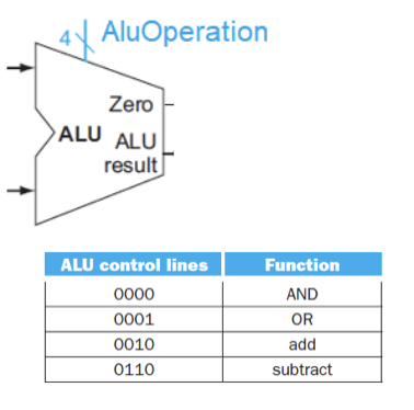
- AND / OR / ADD / SUB
- Data Memory
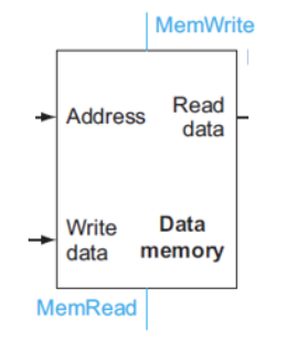
- can read data from data memory only when MemRead=1
- can write data from data memory only when MemWrite=1
- Register file or regfile
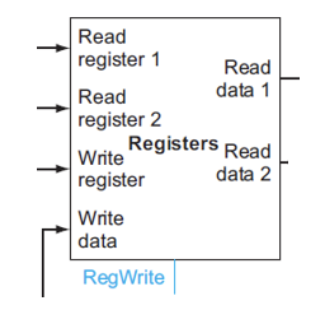
- can read data from regfile unconditionally
- can write to regfile only when RegWrite=1
- flip-flops/registers: store data in circuit
- uses a clock signal to determine when to update stored value
- edge-triggered: update when Clk edge changes from 0 to 1
- Instruction Memory
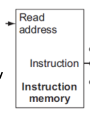
- read instructions
Instruction Types
- R-Type - arithmetic instructions
- read two register operands from regfile
- perform arithmetic/logical op in ALU
- write reg result into regfile
- L-type - load instructions and S-type - store instructions
- Read register operands and immediate field
- calculate mem addr using ALU
- load: read memory and update register
- store: write register value (rs2) to memory
Instruction Steps
- Send the program counter (PC) to a memory that contains code to fetch the instruction - Fetch
- Read one or two registers using fields of the instruction to select the registers to read - Decode
- For load instruction, we need to read only one register, but all other instructions require we read two registers
- Varies between three instruction types: memory-reference, arithmetic-logical, and branches - Execute
- Commonalities include, using ALU after registers
- memory-reference use ALU for address calculation
- arithmetic-logical for opcode execution
- branches for comparison
- Varies again: - Access or write back
- memory-reference need to access the memory containing the data to store or load
- arithmetic-logical must write the data from ALU back into a register
- branch, may need to change next instruction address based on the comparison
Datapath Diagram
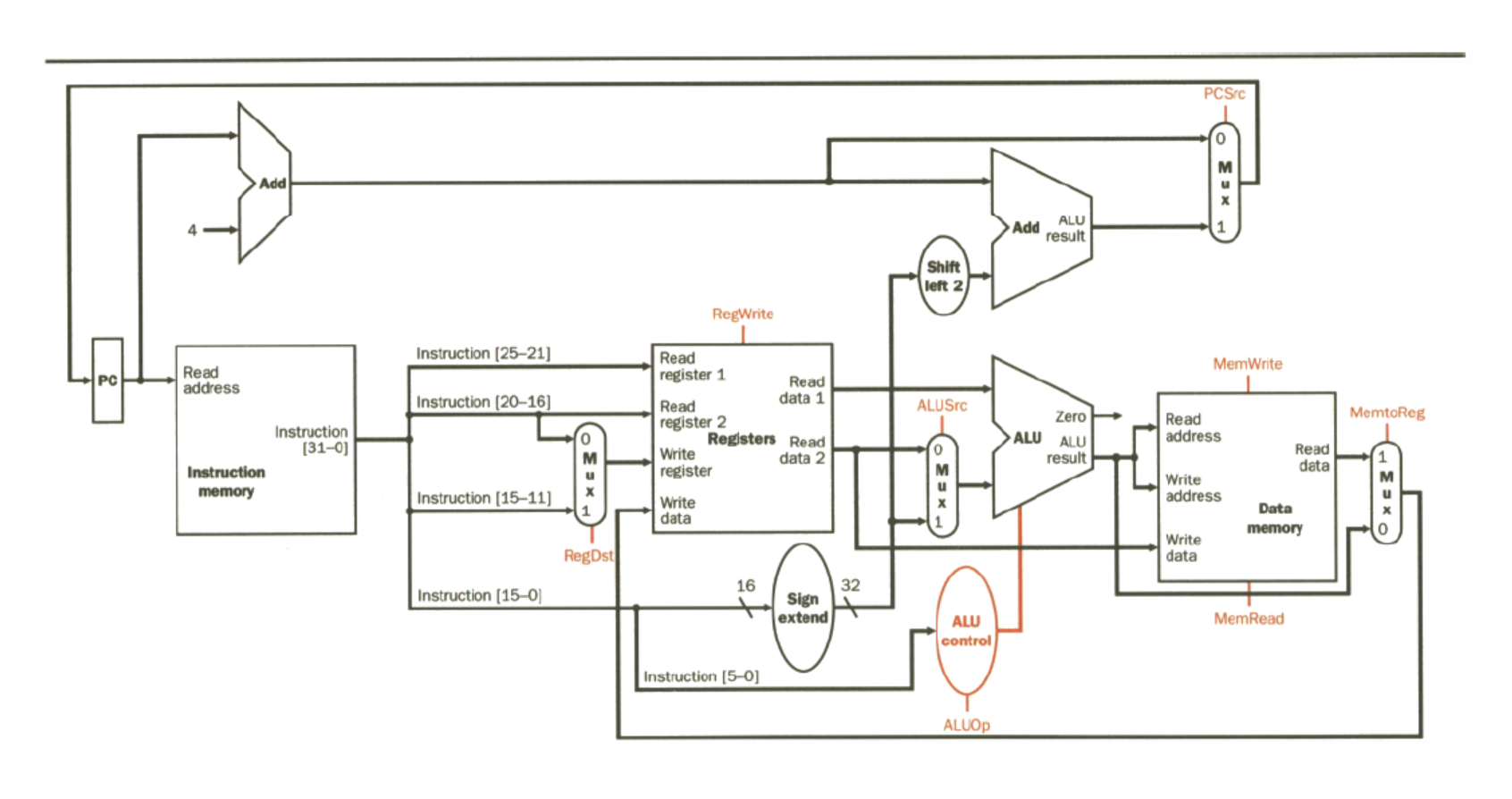
with Control
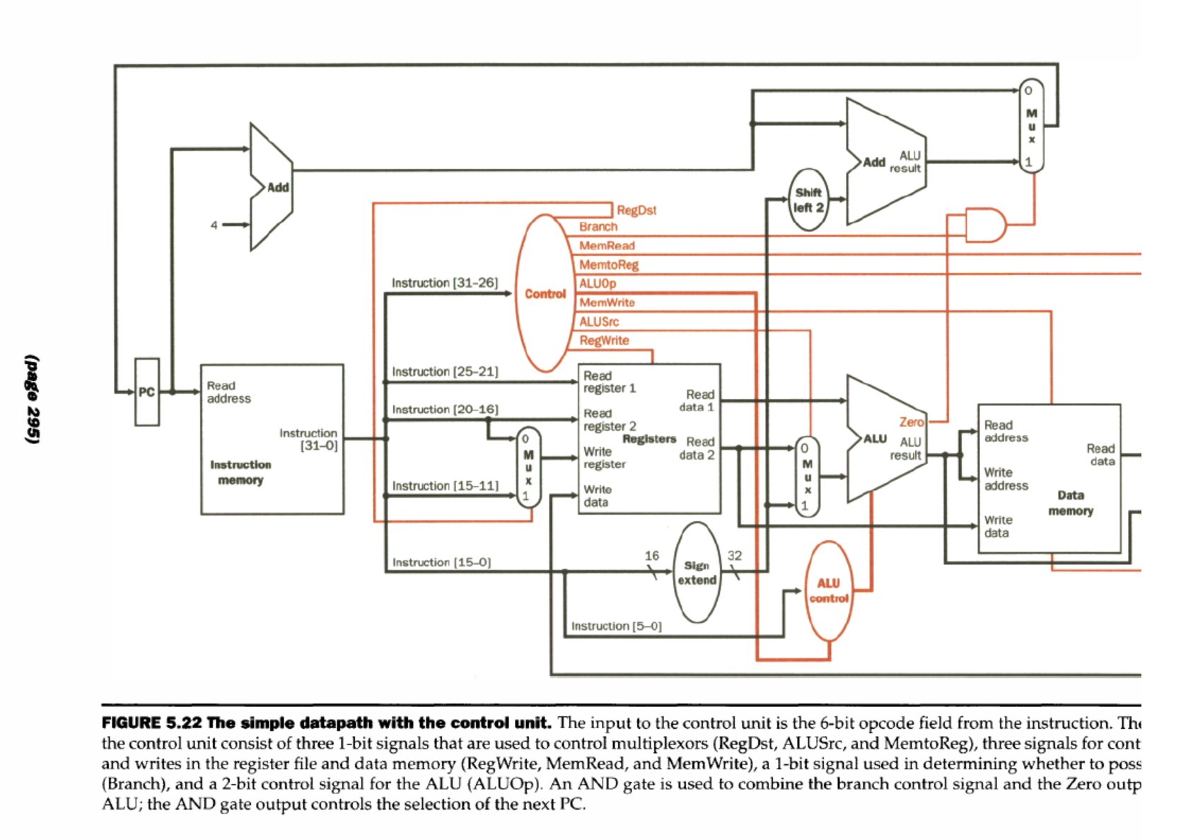
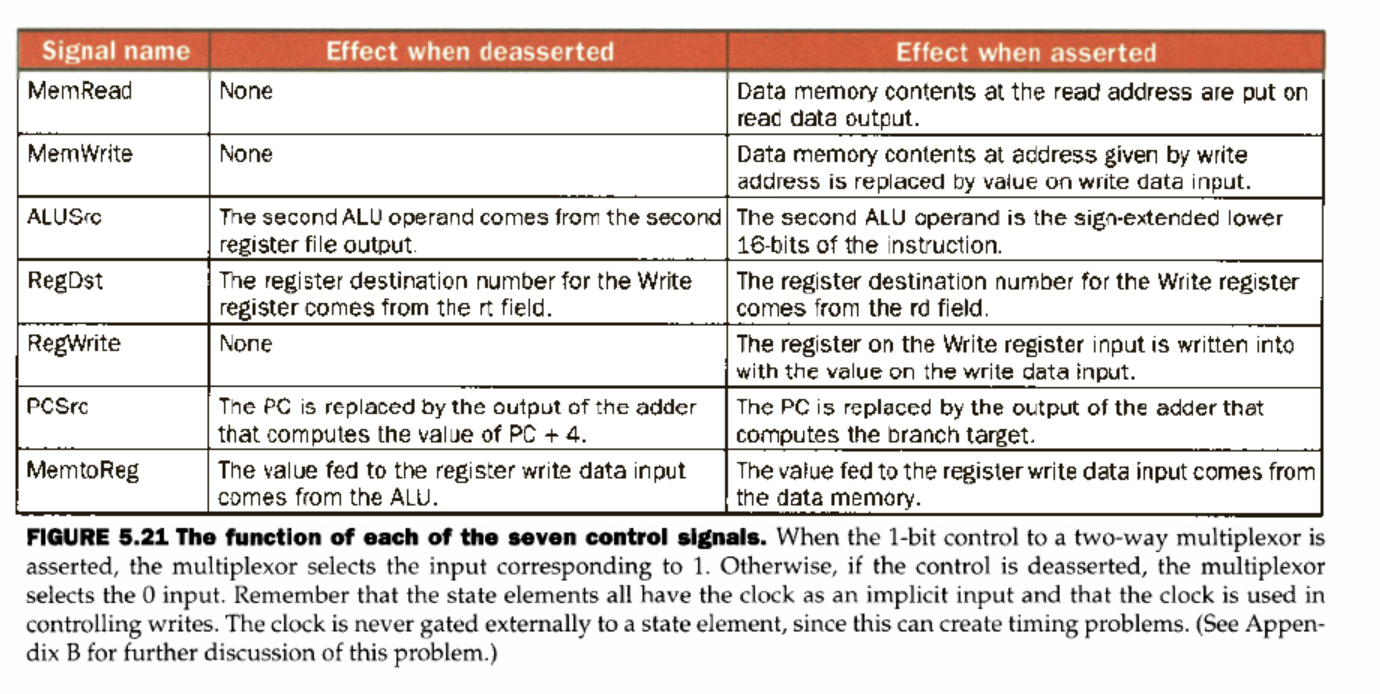
Control
Why is it needed?
- tells the hardware component what to do Derived from opcode
Pipelining
Parallelizing instructions to increase utilization of instructions
- temporal parallelism: the same hardware resource is shared between different tasks at different stages of time
5-stage RISC pipeline
- IF: instruction fetch
- ID: instruction decode and register read (RF)
- EX: execute op or calculate addr
- MEM: access memory operand
- WB: write result back to reg Spread work over hardware over time (amortization) / all hardware used all the time
Execution time
For pipelined, clock period = slowest stage TODO: check old notes on through put
Hazards
When the next instruction in the sequence cannot execute in the following clock cycle due to interdependence between the execution of consecutive instructions
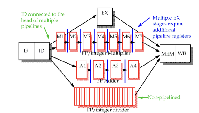
Structural Hazards
When two instructions need the same hw at the same time
eg: FP/integer multipler
- Memory access
- if same physical memory for instructions and data
- Register file
- if R/W to the same register at the same time
- Fast Register file
- don’t worry about structural hazards with R/W, happens on the same cycle
Data Hazard
One instruction has a src operand that is the result of a previous instruction in the pipeline
| Type | Example | Meaning |
|---|---|---|
| RAW (Read After Write) (true dependency) | add $t1, $t2, $t3 sub $t4, $t1, $t5 | The sub needs $t1, but add hasn’t written it yet. |
| WAR (Write After Read) (anti-dependency) | sub $t4, $t1, $t5 add $t1, $t2, $t3 | Doesn’t show up simple in-order pipelines, but if order is mixed it will |
| WAW (Write After Write) (output dependency) | add $t1, ... sub $t1, ... | Both write $t1; order matters. Common in out-of-order CPUs. |
Control Hazards
The execution of an instruction depends on the resolution of a previous branch instruction in the pipeline, branch and jumps
beq $t1, $t2, target
add $t3, $t4, $t5   # Which instruction should actually execute next?
Pipeline stall
wait until hazard is not an issue, inserts NOPs
RAW hazard detection
Compare src and dest registers in ID stage
Branch prediction
Goal: minimize bubbles/stalls
No Prediction
- Control at MEM: stall pipeline until branch resolved (unconditional stall)
- pipeline always stalled for 2 extra cycles
- Control at ID: stall pipeline until branch resolved (unconditional stall)
- pipeline always stalled for 1 extra cycle
Static Prediction
- Always-taken: Assume every branch will be taken.
- Always-not-taken: Assume no branches are taken.
- If correct, no bubbles/stalls inserted
- If wrong, flush pipe, inserting one bubble/stall
- Easy to implement, just continue to fetch PC+4 (until wrong)
Dynamic Prediction
Dynamically change prediction between Taken and NOT taken based on past history of branch behavior
- 1 bit predictor:
- taken → set bit to predict taken
- if not taken → set bit to predict NOT taken
- use lookup table in mem to map branch instruction address to prediction bit
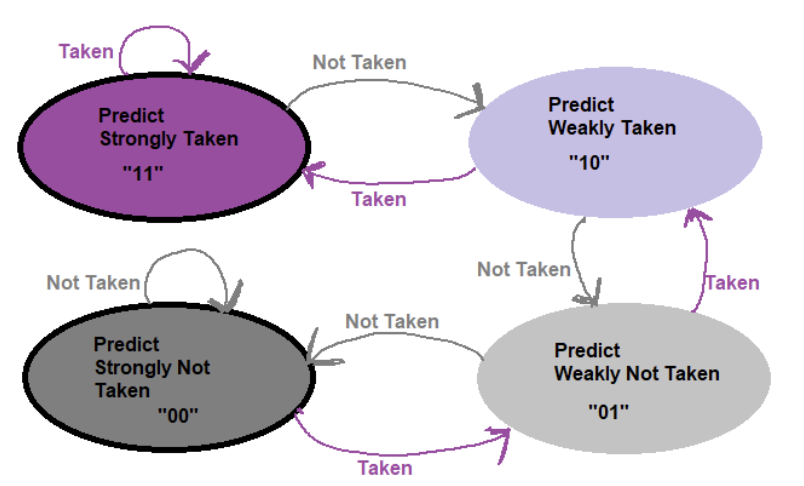
- 2 bit predictor
- predict strongly taken - 11
- predict weakly taken - 10
- predict strongly NOT taken - 00
- predict weakly Not taken - 01
Data Forwarding
Idea: find when the first RAW can take place by passing result into where it’s needed rather then writing to memory
- Prevents more RAW hazards
Scalar vs Superscalar:
- scalar = 1 instruction starts per clock cycle
- superscalar = multiple instructions can start per clock cycle (always pipelined)
Cache
Mem Techs
- Static RAM (SRAM)
- Dynamic RAM (DRAM)
- Flash (non-volatile)
- Magnetic disk (non-volatile, mechanical)
Spacial Locality and Temporal Locality
| Temporal locality | You use the same location (variable or array element) again soon. |
|---|---|
| Spatial locality | You access nearby locations (addresses close to each other) within a short time. |
Cache uses the principle of locality to:
- provide as much inexpensive storage space as possible
- offer access speed equivalent to the fastest memory
- for data in the cache
- key is to have the right data cached
Direct Mapped Cache
- location in cache is determined by (main) memory address
- “Direct mapped”: one choice
Tag and Valid Bits
- check if block in cache?
- use tags, high-order bits of block address
- if empty?
- use valid bit, 1= present, 0 = not present, init 0
Impact of Block Size
- Larger block size = greater miss penalty always
- spending more time in accessing greater amount of memory outside of block
- Larger block size favors spacial locality
- Initially large blocks will lower miss rate and favor spacial locality
- However at larger block size, there would be a limited number of blocks in cache → greater competition → large cache blocks evicted → miss rate increased
Handling Cache Miss
- Stall the processor, while waiting for memory
- Cache miss increases the CPI
Handling Cache Writes
Write-through cache: forcing writes to update both cache and memory
- issue accesses main memory Dirty bit: used to check if it needs to be saved to main memory before being replaced
- prevents unnecessary writebacks Write misses: try to write to an addr that is not already contained in the cache
- Write around: write goes directly to main memory without affecting the cache
- Allocate on write: load newly written data into the cache
Unified vs Split Cache
- Split Cache Design: one cache for instructions and a separate cache for data
- when programs need to access both instructions and data in the same clock cycle
- unified cache: stores both program code an data
- value may be stored anywhere in cache memory = more flexible
- typically lower miss rate
Measuring Cache Performance
Assume no data/control/structural hazards
- CPU Time = (CPU program execution clock cycles + Memory stall clock cycles) x clock cycle time
- Memory stall clock cycles = (Read stall cycles + Write stall cycles)
- Read stall cycles = (Reads/program) x (Read miss rate) x (Read miss penalty)
- Write stall cycles
- write miss - fetch from lower level mem, allocate on write
- write buffer stall - write buff is full and need to wait
- Write stall cycle = (Write/Program) x write miss rate x wrtie miss penalty + write buffer stalls
- In most write through impls:
- Memory stall clock cycles= (Instructions/program) x (Misses/Instruction) x Miss penalty
Average Memory Access Time (AMAT)
- Takes into account hit time, which increases for larger cache sizes
- AMAT = Hit time + miss rate * miss penalty
- Example
- CPU with 1ns clock, hit time = 1 cycle, miss penalty = 20 cycles, I-cache miss rate = 5%
- AMAT = 1 + 0.05 × 20 = 2ns
- 2 cycles per instruction
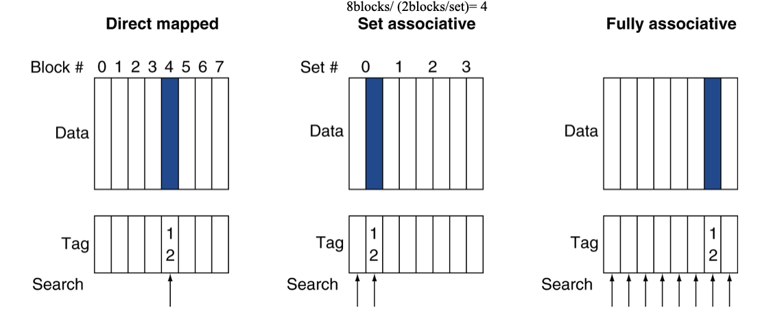
Associative Caches
Direct Mapped Cache is 1:1, Associative 1:many
- Fully associative
- allow a given block to go in any cache entry, requires all entries to be search at once (expensive)
- n-way set associative
- each set contains n entries
- block number determines which set
- (block number) % (No. of sets in cache)
- search all entries in a given set at once
- n comparators (less expensive)
Increased associativity decreases miss rate but with diminishing returns
- more items in cache = less miss
- more order in cache = less item in cache, less expensive search
Replacement Policy
- Set associative
- prefer non-valid entries, else choose
- LRU
- chose one unused for the longest time
- Random
- give approx. the same perf for high associativity
SA Cache Calculations
Given cache config: 32KiB, 64B blocks, 4-way set associative, 32-bit address
- Cache data size = 32KiB =
- Block size =